
204F-1
Click here to read my story about the aquisition of the Collins 204F-1 as recently published in DX-Magazine.
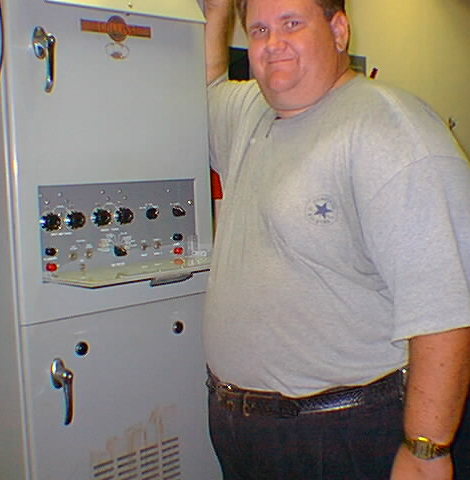
Here I am standing next to my beatiful Collins 204F-1(AM-2374/URT), two channel, 3 stage RF Linear Power Amplfier, which covers 2-30Mhz.
Designed and built begining in the late 1950's through the early 1970's for commercial and government applications
For the 1959 catalog page listing the 204F-1 click here.
This beauty requires only 0.1 watts to produce 2.5Kw continuous output (5.0Kw input) if used as designed. The amplifier will actually produce much more than the rated output when used in ICAS type of service from its pair of 4CX1000A tubes.
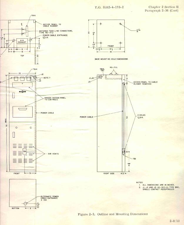
The military designation is AM-2374/URT, Amplifier, RF, Transmitter, 2-30 MHz, 2.5 KW (PEP), 50 Ohm output impedance, part of AN/URT-18. 70 in h x 20 in w x 22 1/4 in d. 220-440 vac, 60 Hz single phase. By the way the AN/URT-18 is Radio transmitter set, HF, CW & SSB, 2.5 Kw, major component AM-2374/URT. Basically it is the combination of an exciter and the amplifier.

This amplfier is a real monster, see the separate photos of myself (5' 11") and my friend Bill, KC2CNB standing in front of the unit. It should be on a concrete floor, as it weighs in at 600 lbs., I had to reinforce my wood floor at the current QTH. It must be powered from 220 volts or 440 volts, at peak it draws 6 Kilovolt amperes to provide over 2.5Kw output continuous keydown ! which is way too much for legal amateur radio operation obviously.
It is a three stage power amplifier that is ment to be driven from a low power exciter (transverter jack on TS-930S works great) of less than 1/2 watt peak. The first stage is a 6CL6 pentode operating in Class A, followed by a pair of 6146 tubes operating in Class AB1, the third stage is a pair of Eimac 4CX1000A tetrode tubes as a Class AB1 voltage amplifier covering 2-30 Mhz. Since the grid is tied to the cathode, no grid amplification takes place. Although the power gain is relatively low, linearity is excellent. Yes, this thing is a full conservitively rated 5Kw plus input continuous duty amplfier, (capable of 4.0Kw plus on transmit ICAS) with two completely separate input and output tuning networks for true QSY from channel A to channel B or let's say 20 meters to 10 meters.
My amplifier exists in its full factory configuration. However these units can easily be modified to bypass the first two stages and swamp the input with non-inductive loading network to drive one (or both!) of the 4CX100A tubes directly from a 100w class radio instead of using and exciter or a radio with a transverter output drive port.
My particular unit was made for the U.S. Air Force and sold as surplus to a company that I once worked for that bought the unit to test antennae with at 2Mhz.
This amplifier follows the designs of many Collins radio equipments begining in the late 1950's. It uses many components that are in other Collins commercial equipments including the popular S-Line. It has the same styling and paint of the S-line as well, this unit is the big brother of the popular 30S-1 amplifier. Many amateurs are familiar with the 30S-1, however not many know anything about the 204F-1. I have done a lot of research into the history of these units and know the the story of this one well and I have discovered many interesting things and contact with a number of ex-Collins employees that built and tested these units.
Click on any picture below for higher resolution version or come back soon and visit the sectional pages for many more photos that are currently being created.
Plate Dissipation (Max.) 1,000 Watts
Screen Dissipation (Max.) 12 Watts
Grid Dissipation (Max.) 0 Watts
Frequency for Max. rating (CW) 110 MHz
Here is the RCA data sheet in .PDF format on the 6CL6
first stage driver tube.
Here is the RCA data sheet in .PDF format on the 6146
second stage tubes.
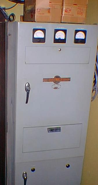
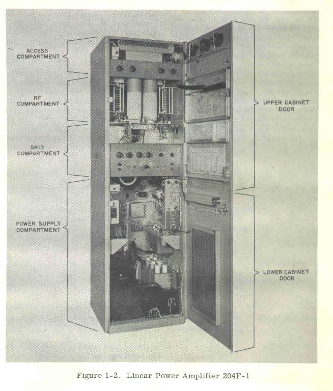
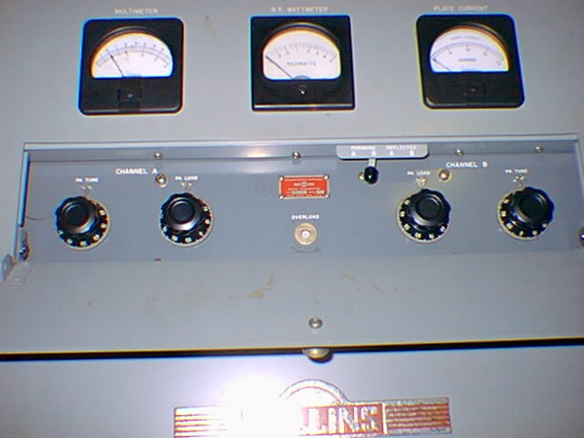
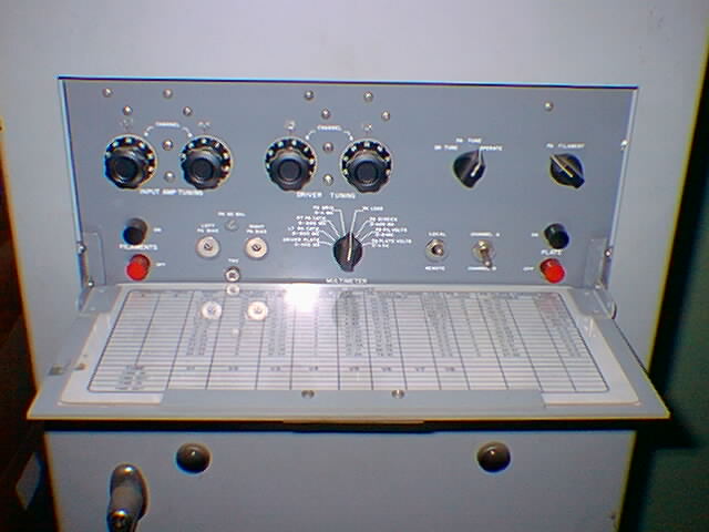
Here is the whole top 2/3rds of the unit. The bottom houses the power supply, it is all in a 6 foot self contained cabint with hinged front door. The upper and mid part of the door has two fold down panels for access to input and output tuning controls. The top panel has three meters to monitor all critical parameters, the wattmeter is a built-in Bird meter!
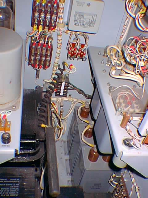
The picture below shows the front door open and the final section, input tuning section and power supply sections.
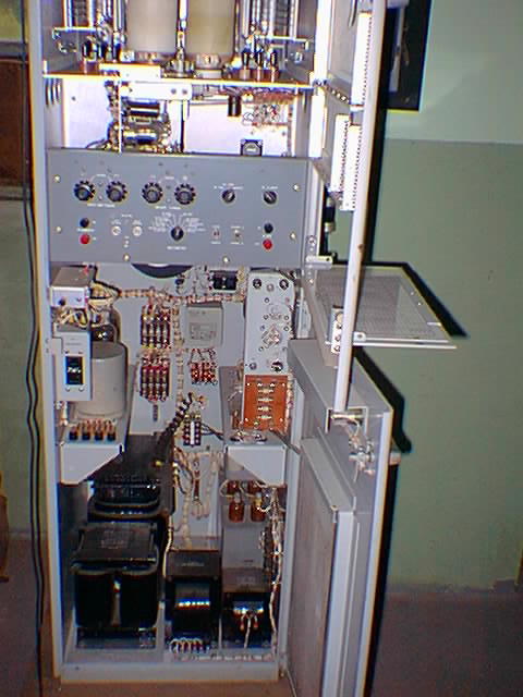
Power supply section:
Power on accumulated hours meter.
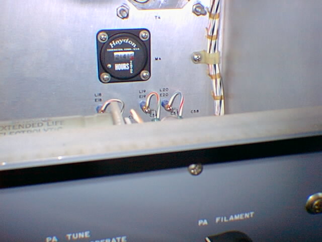
Click here for more power supply photos
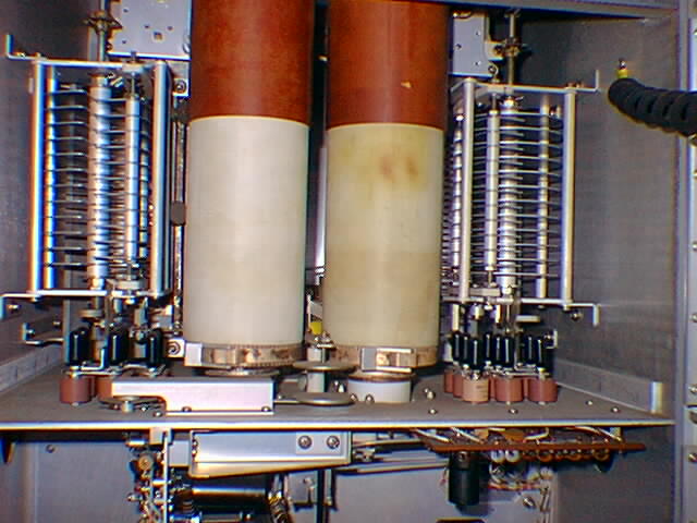
Final tank and chimneys:
2nd driver stage 6146 tubes.
Click here for more RF section photos
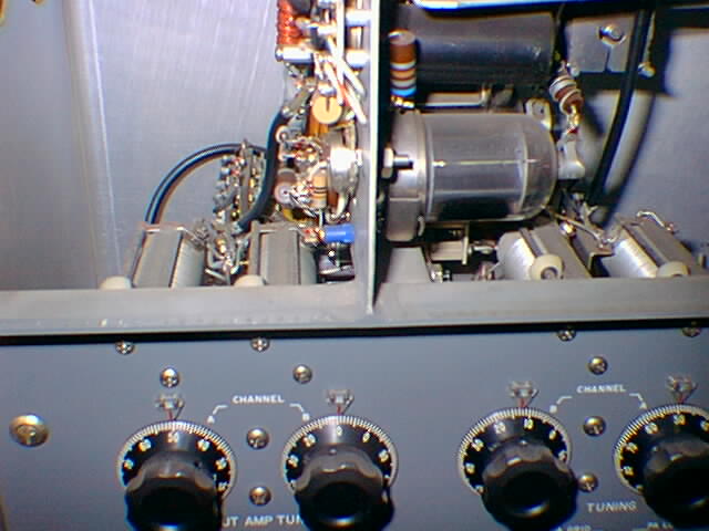
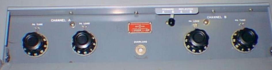
Here is a close up the plate tuning and Channel A and B switches.
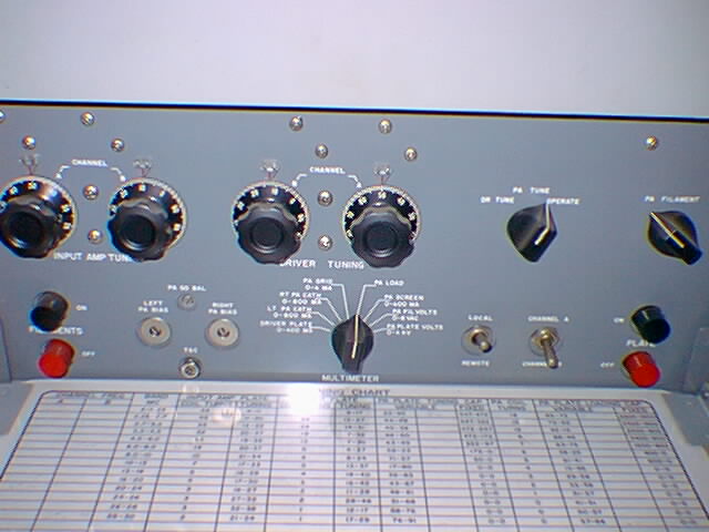
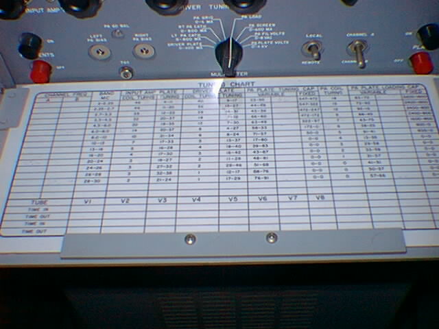
Here is a close up of the input tuning panel and preselected settings guide when the door is opended up for tuning either or both channel A/B.
Click here for more exterior photos
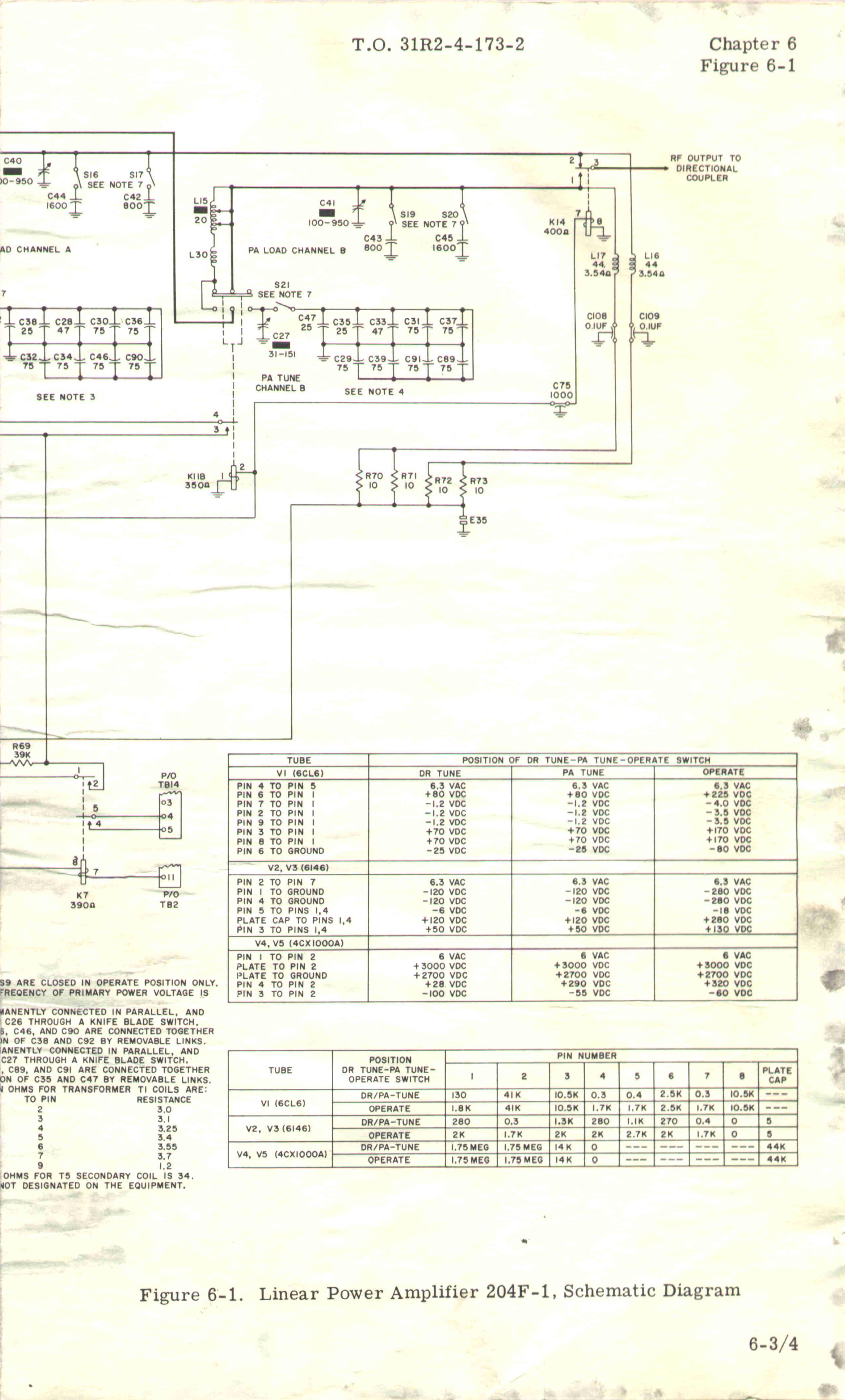
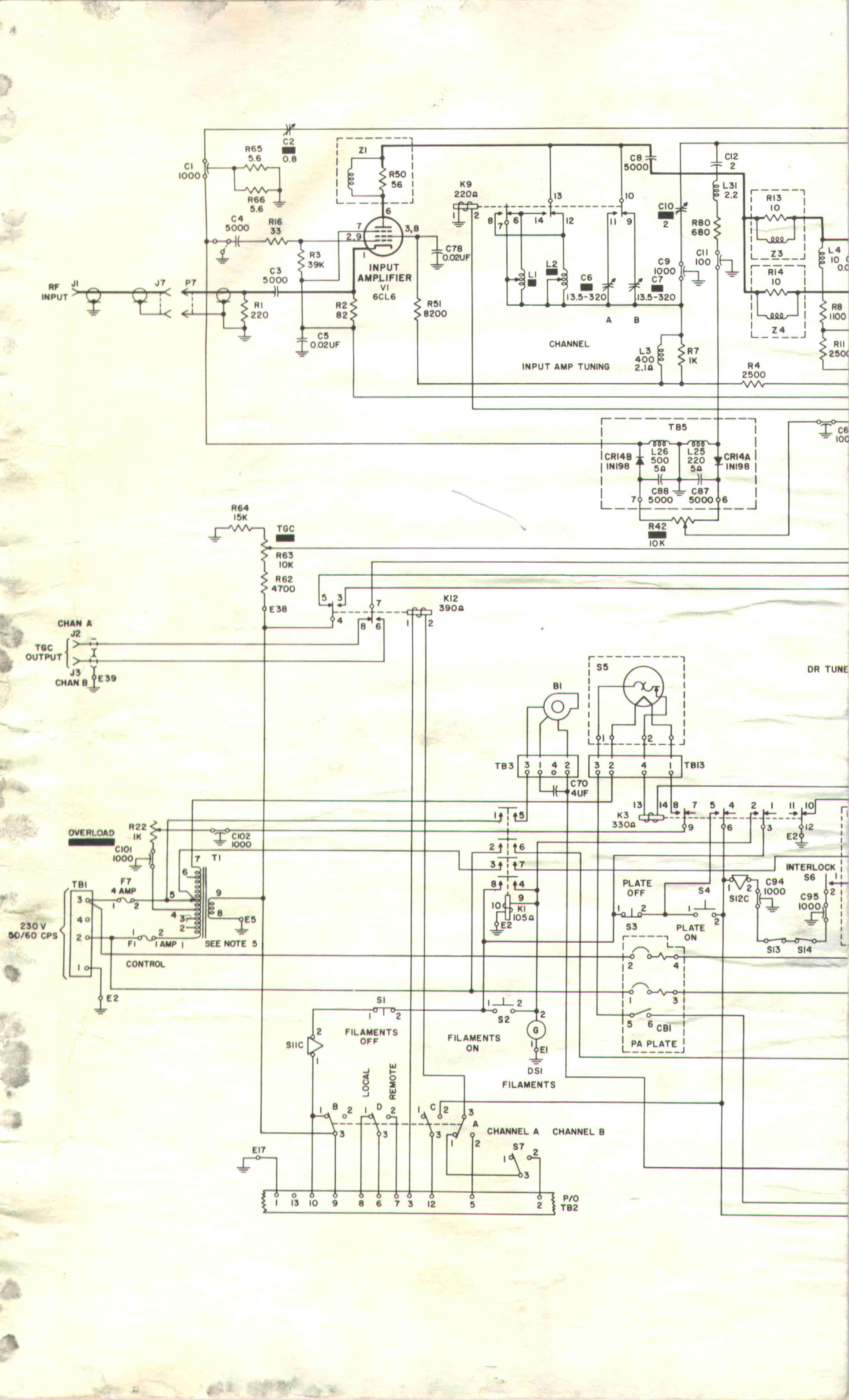
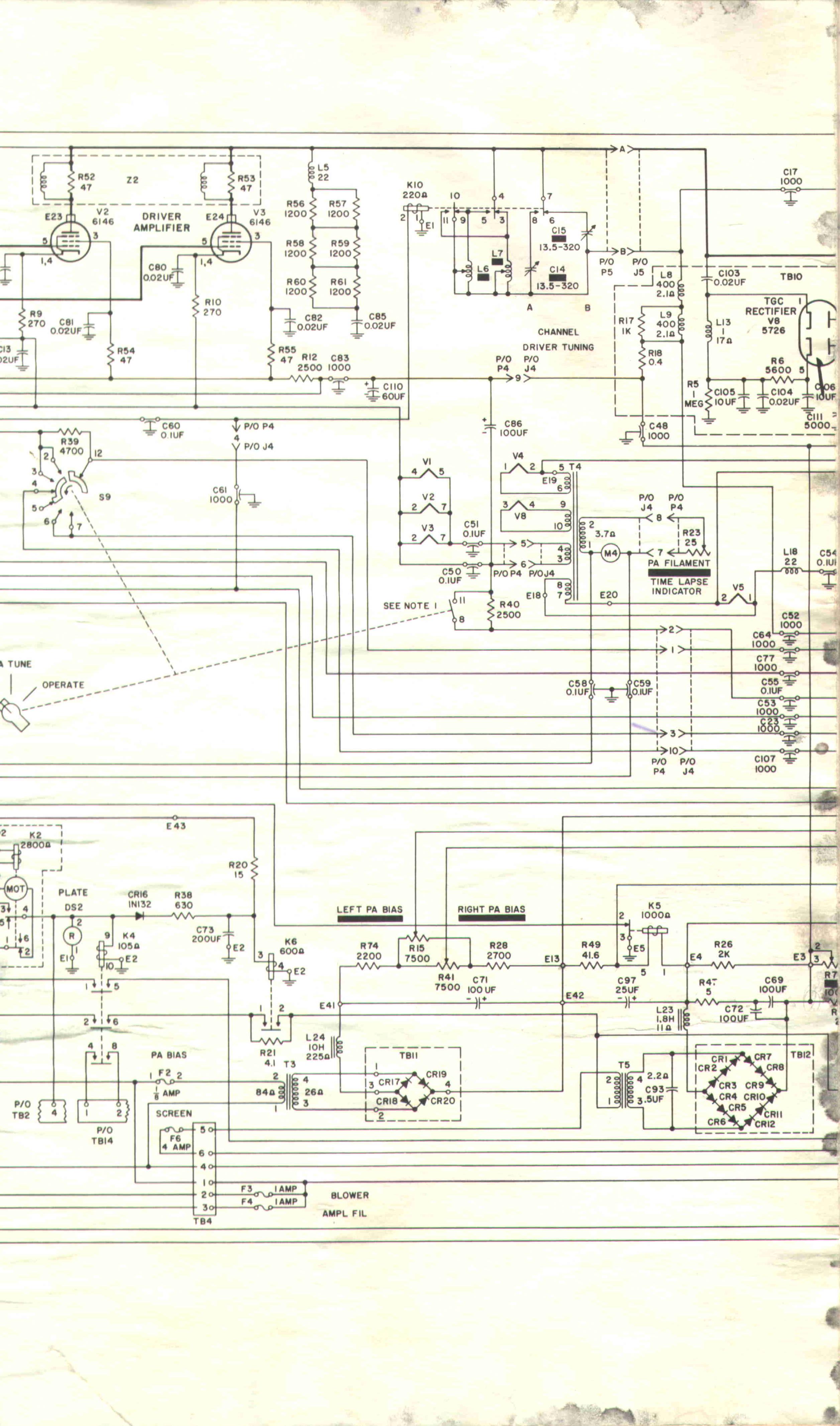
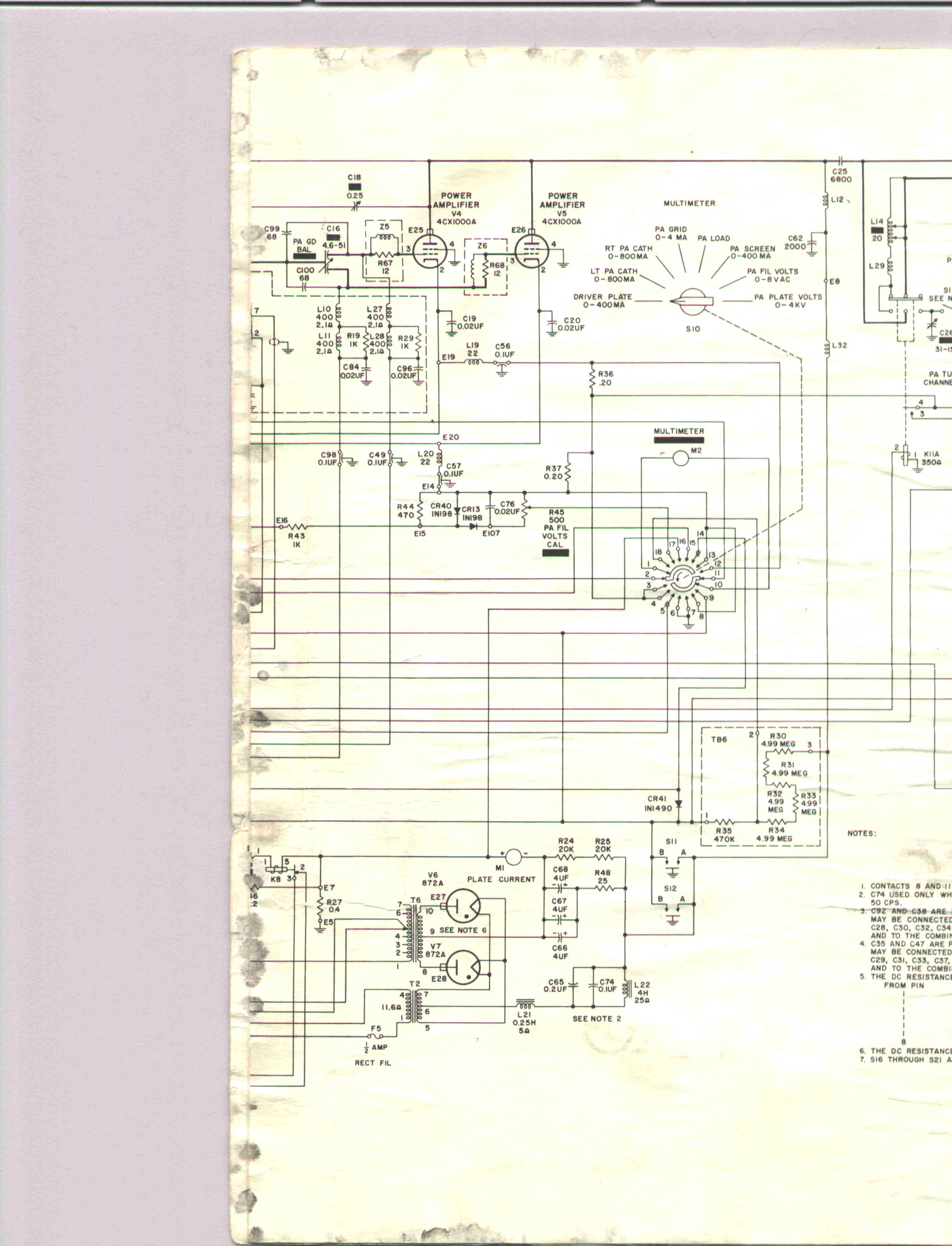
Below is the amplifiers schematic broken down into parts A, B, C and D. I would like to figure out how to make minor modifications to the circuitry to allow operation down to 1.8 Mhz.

Click here with right mouse to download full size schematic part A as JPEG file

Click here with right mouse to download full size schematic part B as JPEG file

Click here with right mouse button to download full size schematic part C as JPEG file
Click here with right mouse to download full size schematic part D as JPEG file
The U.S. Air Force Technical Manual for the 204F-1 is T.O. 31R2-4-173-2
Manuals for many of the older Collins BIG BOY amps can be had from Surplus Sales of Nebraska, they are very much over priced ! The website is: http://www.surplussales.com, at which they advertise they have:
PUB-COL-204F-1; Linear Amplifier, copy $145.00 USD
PUB-COL-204H-1; Linear Amplifier, copy $145.00 USD
PUB-COL-208/U10; 208/U-10 Manual, copy $175.00 USD
PUB-COL-208A-1; 208A-1 Power Amplifier Manual, copy $125.00 USD
PUB-COL-208A/1A; 208A-1A Power Amplifier Manual, copy $75.00 USD
PUB-COL-208U-10; 208U-10 Power Amplifier Manual, copy $145.00 USD
Collins 180Z-1 Automatic Antenna Tuner:
The Collins 180Z-1 automatic tuner, weighs 98+ lbs, can handle 10KW PEP and 5KW average, continuous duty, from 2 to 30 Mhz. The 180Z-1 was designed for use with the 204H-1 and manually tuned transmitters like the 204F-1.
The 180Z-1 manual states: The Collins Automatic Line Flattener 180Z-1 will match any impedance with a 3:1 vswr to a 50 ohm line at a peak power of 10 KW. It will tune to a new frequency on the carrier frequency with the carrier set to a reduced level. With an antenna change and no change in frequency, the 180Z-1 will tune to the new impedance on the SSB voice modulation alone. No reduction in power is required. The 180Z-1 may also be tuned manually using the front panel controls and the built-in multi-meter. The tuner requires no control or band switching information from the transmitter. It does however have an output to the transmitter indicating that it has completed its tuning cycle thereby allowing full power and also sends indications that it is tuning. The front panel multi-meter allows for manual tuning and visual checks. The unit consists of three variable tuning elements, two servo amplifiers and associated discriminators. The tuning elements consist of a windup coil, a roller coil and a vacuum capacitor connected in a T network. The loading circuit consists of a roller coil and capacitor mechanically ganged and driven through a gear train by the loading servomotor. The phasing circuit consists of a windup coil connected to the transmitter side of the variable capacitor is driven by the phasing servomotor through a gear train. The ganged elements of the loading circuit are driven until the magnitude of the impedance as seen by the loading discriminator is equal to 50 ohms. The phasing windup coil is driven until the phase angle as seen by the phasing discriminator is zero. Built with the highest quality components this is a mechanical marvel.
For more information please click here to send e-mail.
.

Entire contents Copyright © 1999-2001 by Stephen B. Hajducek, N2CKH. All Rights Reserved Worldwide.