The satellites sites for the 6m repeater are under way, read the details below. The first voter will be a GE unit after all.
The additional on site co-hosted repeaters on 2 meters, 1 1/4 meters, 70cm (440Mhz) all came on-line during last summer and fall. The purpose of these systems are to provide as many points of access for users in the local amateur community to have access to the features of the hub.
Plans are now underway to add additional offsite repeaters to mix which I am involved on 1.25m, 70cm and 900Mhz.
August 2002 Update:
Development efforts are proceeding nicely.
There are many things yet to be done. Unfortunately a key item, the PR RI-400 controllers mentioned below have been delayted. A number of things must take place in a specific order before the RI-400 will be an issue, without it however we can NOT have the full integration of all ther repeaters that is desired. The following is a listing that is not necessarilly in any order.
As can be seen in the photo's by clicking here, I have been busy shopping around and buying equipments to assemble the entire hub.
For details on the the future plans please read all below, I welcome all questions and suggestions.
1. Satellite Receiver Sites for 6 meters.
As the purpose of 53.430 is to provide the Ocean/Monmouth County NJ area with a reliable 6 meter system with good coverage, I have decided to fill in the holes in our coverage with remote satellite receiver sites linked back via UHF using U.S. made Motorola 25-54Mhz Mitrek radios and Canadian made Motorola 406-430Mhz Mitrek radios paired together.
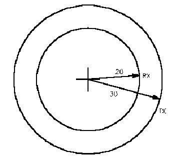
The current 6m mobile coverage (20-50 watt) of the system is not bad, considering the repeater antenna gain, elevation above sea level and elevation above ground level. However the power level and antenna height and gain differences between the repeater station and mobile/hand helds results in a coverage area that is much larger for the repeater transmitter coverage than its ability to receive stations that are not fixed base stations. Click here for topographical map overlay display of the current system mobile coverage. The simple graphic below depicts the current average mobile coverage of the system by the inner circle for receive of mobiles to 20 miles reliably and the outer circle for solid repeater tranmit beyound average mobile access to 30 miles. Mobiles can receive the repeater some 40 to 50 miles away however getting back in is tough with 1/4 wave mobile antennae.
Basically more than half of what would be the repeaters reliable mobile coverage area in square miles is lost due to use of 1/4 mobile antennae. At 6 meters antenna gain is a problem, as beyond easily installed unity gain mboile antennae and for fixed station unity gain 1/4 ground plane your next step up to a much larger 5/8 wave ground plane and folded dipole arrays. Even then the gain is not that great, when mounted on a monopole or tower these antenna are suitable to use, however in our case the mounting does not allow these large antennae systems. The standard mobile antenna is only a 1/4 wave radiator and for portables (HT's) the situation is even worst.
To over come this, a receiver voting system will be installed at the N2CKH/R hub. Receiver voting sytems are quite common in Public Safety radio systems, the main advantage of receiver voting is the apparent increase of range offered to portable and low powered mobile units. So by increasing the number of active receivers out and aobut in the system, the odds increase dramatically that these lower powered units will be within range of the system, and noise will be minimized.
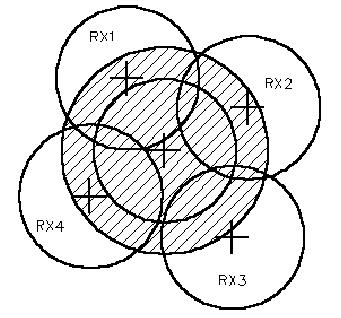
The voting selector will evaluate all signals present on each input (Motorola Mitrek UHF link radio receiver) and select the one with the least noise. The plan is to have four (4) VHF low band satellite receviers (RX1-RX4) on 52.430 with PL decode of 131.8hz at all times to the North West, North and North East as well as one to the South of the system.
Basically RX1 will be in the Englishtown/Manalapan (NW) or Freehold/Mananalapan (N) area. Then RX2 in the Red Bank/Eatontown or Long Branch/Ocean Township or Asbury Park/Neptune (NE) area. Then RX3 will be in the Bayville/South Toms River (SE/S) area. Finally RX4 will be in out in the the Lakehurst/Brownsmills (SW) area. Should additional sites be required the voter that is planned for use will have three (3) spare inputs available. At the hub a matching UHF receiver for each satellite site paired to a receive multicoupler to one UHF antenna will feed the voter.
In the following graphic the shaded area represents the repeaters transmitter coverage area and the large inner circle the main receiver coverage area with each of the four satellite receivers smaller circles those receivers coverage area. Much of the coverage area of the main repeater receiver is now duplicated by the satellite receivers, such overlapping coverage reduces signal loss or fading caused by the terrain and surround structures of the mobile/portable station. With the voter selecting the receiver with the best signal on the source, we are now quarenteed that the repeated signal will be the best possible.
In addition, the key to a smooth satellite receiver system is to have all the remote link transmitters and receivers of the same manufacturer and model (Motorola Mitrek's) to get the best results. Another trick is to use discriminator audio throughout the linking equipment and PL decoders for the detection of COR and set the link transmitters all to exactly 4.5Khz deviation. If all this is done, a user should not be able to detect a voter system is being used due to the matched equipment. The one exception is that the current 6m repeater uses and will likely continue to use the GE Master II reciever.
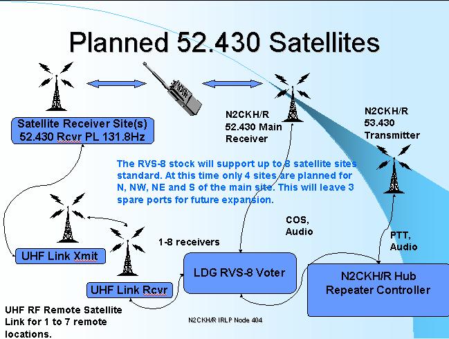
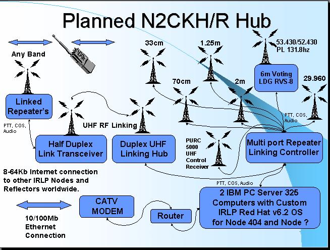
For a planned block diagram see the image below, the voter was going to be GE unit but may end up being the LDG RVS-8 eight receiver voting system. The system will utilize Motorola Mitrek UHF radios for the link transmitters and receivers and Mitrek 25-54Mhz low band radios for the 52.430 receivers.
The implementation of this system is dependant on all the sites be arranged for and equipments being configured. The pictorial below is a screen capture from an MS-Power Point presentation recently created for use at local area radio clubs and schools.
2. Enhanced Repeater Controller.
New repeater controllers must be integrated into the system to achieve the desired goals of the entire N2CKH/R hub configuration. The final decision is the Pacific Research RI-300/RI-400 series.
The need for this is to have all the local repeaters, linking hub, IRLP nodes and other features remotely linkable and controllable as seamlessly as possible. With this capability, egress into the system via any RF point of entry will allow for connection to any or all ports on the hub as configured.
When this controller system goes on-line, except for the 6m repeater satellites which will always require a 131.8hz PL tone, access to the main 6m repeater receive and all repeaters will support multiple PL tones. This support is being provided to allow users of older amateur and commercial gear to get into the system without the need of updating their equipment.
Each co-hosted repeater will have a primary decode/encode PL tone, it
will be the primary PL tone that will be regenerated on the repeater
transmitter at all times as follows:
6 meter: 131.8hz
2 meter: 127.3hz
1.25m..: 156.7hz
70cm...: 141.3hz
900Mhz.: 123.0hz
It is planned that there will be times when NO PL tone will be required for access on the 6 meter. However, even when NO PL is required for access, there will still be a PL tone regenerated on the repeater transmitter. The 6m satellite sites will always require PL. The lack of PL on the main receiver is to permit out of area operation with stations during the yearly Sporatic-E band openings. In 2001 we had stations from 12 states into the system from as far away as California.
The PL tones that will be supported on each repeater for complete normal
operation will vary for each band with the main PL tone being the regenerated
tone on the transmitter as follows:
6 meter: 131.8, 136.5, 151.4, 156.7
2 meter: 127.3, 131.8, 136.5, 151.4
1.25m..: 156.7, 131.8, 136.5, 141.3
70cm...: 141.3, 127.2, 131.8, 136.5, 156.7
Also note, that each repeater will support Digital Coded Squelch (DCS) with an input DCS Code setting of 031 for normal operation. The repeater will still ONLY regenerate the primary PL on that transmitter even when a user is coming in with DCS, so the user must be DCS encode only, unless they can also do split DCS/CTCSS. DCS requires all radios to on frequency and good deviation to work well click (DCS) to read more.
The system will also be configured with PL/DCS pairs that will allow for local operation of each co-site hosted repeater without their transmissions propagating to other repeaters on the system and the internet even if those links are active. This will effectively allow for the use of one the local repeaters for two-way conversations will allowing eavesdropping on the other activity. The PL tone for this will be: 165.5hz and the DCS will be: 315
Other tones may be supported upon request. Just remember that the use of other than the standard tone for a given repeater with still result in the standard tone being regenerated on the repeater transmitter thus you will NOT be able to use CTCSS Encode/Decode or DCS Encode/Decode using a supported non-standard tone unless you can do split tones.
Special Tactical Encoding/Decoding of PL/CTCSS and or DCS can be supported for Emergency Management and Special Events as required where both the the Decoded and Encoded codes can be the same as well as multiple pairs for sub group applications.
3. Additional N2CKH/R VHF/UHF Repeaters.
There are also plans for 33cm (902Mhz) and 23cm (1296Mhz) repeaters to be added to the mix as well in a year or two.
The 1.25 meter, 33cm and 23cm systems are a two fold focus, as with 6 meters, the use it or loose it scenario applies. Also important is access to the hub by the Novice class licensee as 1.25 meters is the only VHF band that a Novice has access to. Then comes the 23cm band.
Also being integrated into the system is a Motorola PURC5000 UHF receiver for the hub control link capability. It will be fed off the UHF receiver multicoupler feeding the 6m satellite receivers.
The 33cm repeater will be the last item added to the system in late 2002 or in 2003. It will be Motorola Maxtrac based and use a Wacom duplexer and Db Products circulator. The anntenna and other items have not be determined.
4. Planned Linking Hub Configuration.
When the UHF linking hub comes on line the following will be available on the hub at Lakewood with additional network connections accessible via the systems that link to the hub.
The ports will tenatively be configured as:
RI-400 HUB Controller 1:[Supports linking & IRLP node 2 access/command & control for off-site repeaters]
Port 1: UHF Linking Hub
Port 2: Linux Server 2: IRLP Node 728
Port 3: NOAA EAS/SAME Wx Receiver 2
Port 4: Open 911 Autopatch
RI-400 HUB Controller 2:[Supports co-hosted repeaters for IRLP Node 1 access
Port 1: 6m Repeater
Port 2: Linux Server 1: IRLP Node 404
Port 3: NOAA EAS/SAME Wx Receiver 1
Port 4: Open 911 Autopatch
RI-300 HUB Controller 3:
Port 1: 2m Repeater
Port 2: Switchable: 10m FM Remote Base
Port 3: Auto Patch
RI-400 HUB Controller 4:
Port 1: 1.25m Repeater
Port 2: 70cm Repeater
Port 2: DX-Cluster Server Voice Spots
IRLP node 2 will be on the linking hub.
The four (6m, 2m, 1.25m, 70cm) site co-hosted repeaters will be accessible via the linking hub as well. However the 6m repeater will not normally be on the hub as it has IRLP Node 1 on it.
The system will be very versatile in the its configuration capabilities as to what commbination of ports can be connected together and bridged via off site linking. This configuration will allow a user on any RF ports to to link to any port(s) from the port they came in on if it is not already linked when the user first accesses the system.
This will allow for some creative programming as to day-of-week/time-of-day pre-scheduled programming and on-the-fly linking combinations. To even include say linking another repeater system in another part of NJ let's say that has an IRLP node into the system and then connecting with our 2nd IRLP node to another IRLP node or reflector and linking those ports together or whatever combination one could imagine.
Here's a scenario for you that I will make use of, say I am on business travel and have access to an IRLP node. I will be able to dial up on IRLP node 1 and connect directly to the Autopatch of controller 2 to make a phone call locally... way cool ! Think of all the combinations and applications for daily and emergency operation.
As you can also see their are two (2) NOAA Wx Receivers for an automatic SAME warning condition. Their is actually one recevier that will feed two (2) decoders as the two RI-400 controllers will not usually be linked as that would like the tow IRLP nodes. You can think of the system as two islands. The off site repeaters can dock at the first island (RI-400/IRLP Node 2) and the local repeaters can dock at either island (RI-400/IRLP Node 1). When required for special purposes and emergency configurations the entire system can be interconnected in demand.
The DX-Spotting system is still to be MS-Windows based. If at all possible it is planned to make use of one of the Linux servers and IRLP interface for DX voice spots. However no one have written software and scripts to do this yet and I have code written and proven for MS-Windows. So at first this will likely be an MS-Windows box. Later as I learn more about programming for the Linux OS I will port code to run the DX-Spotting on Linux.
The 10m remote base in on the controller tied to the 2m repeater. As we could not allow 1.25m Novices access to 10 meters this seem like a good place for the remote. We trust that all Novices license holders will take note to messages informing all users of the 10m remote being active.
In addition the AERIALS 443 repeater system in Ocean Township, Monmouth county will be linked into the hub adding its overlapping coverage to the mix.
The 2nd IRLP node is in place and currently accessible only via the AERIALS 443 repeater system.
The next repeater to go on-line at the hub in Lakewood will be the 70cm then the 1.25m system.
Next the linking hub will follow and the 2nd IRLP node will be moved to the hub so that other remote systems can connect to it in addition to 443.
Stay tuned as many things will happen during the Summer and fall of 2002 with everything to come together by the end of the year if all goes well.
As always, comments and suggestions are most welcomed.
Please click here to send e-mail.

Entire contents Copyright © 1999-2001 by Stephen B. Hajducek, N2CKH. All Rights Reserved Worldwide.